Axis
- Povl Filip Sonne-Frederiksen
- Projects
- January 1, 2021
Table of Contents
Parametric design tools like Grasshopper have democratized complex geometry creation. Industrial robots can fabricate these forms with incredible precision. But there’s a gap: translating digital designs into robot instructions typically requires manual coding in manufacturer-specific languages, a workflow that’s both tedious and error-prone. For designers working with ABB robots, this means learning RAPID—a programming language far removed from the visual, parametric thinking that defined their design process in the first place.
What if your design software could speak directly to the robot? What if simulation, code generation, and even real-time control could happen inside the same environment where you design?
Introducing Axis
Axis is a Grasshopper plugin that bridges this gap between parametric design and robotic fabrication. Co-created with Ryan Hughes, Axis brings ABB robot programming (with partial KUKA support) directly into Grasshopper, enabling seamless workflows from concept to fabrication.
The plugin was developed at Aarhus School of Architecture, which had acquired several ABB robots including an IRB6620 and multiple IRB120s. Starting as a collection of Grasshopper scripts, Axis was rewritten as a native C# plugin to meet growing feature demands and performance requirements. It aims to bring robot programming closer to the design environment, enabling fast experimentation while abstracting away the technical knowledge required for writing RAPID code—ABB’s robot programming language—without sacrificing control.
While there now exist several excellent tools in this space — Robot Components, TACO, and Robots by visose — at the start when Axis first began there was only KUKA prc which was explicitly only for KUKA robots, hence the need for a similar tool but with ABB support. Axis’s strength is in its trade-off between a simple user interface, allowing students to quickly pick it up and start using it, while still allowing for a lot of customization and control for advanced users.
How It Works
Define Your Toolpath
Axis generally offers two approaches to defining robot positions, each suited to different use cases:
Plane Targets define where the tool center point (TCP) should be in 3D space, with full orientation control. In Axis this is done by using a Grasshopper plane — location and orientation.
Joint Targets give you direct control, specifying exact angles for each joint. This is useful when you need precise control over the robot’s configuration or when specifying home positions.
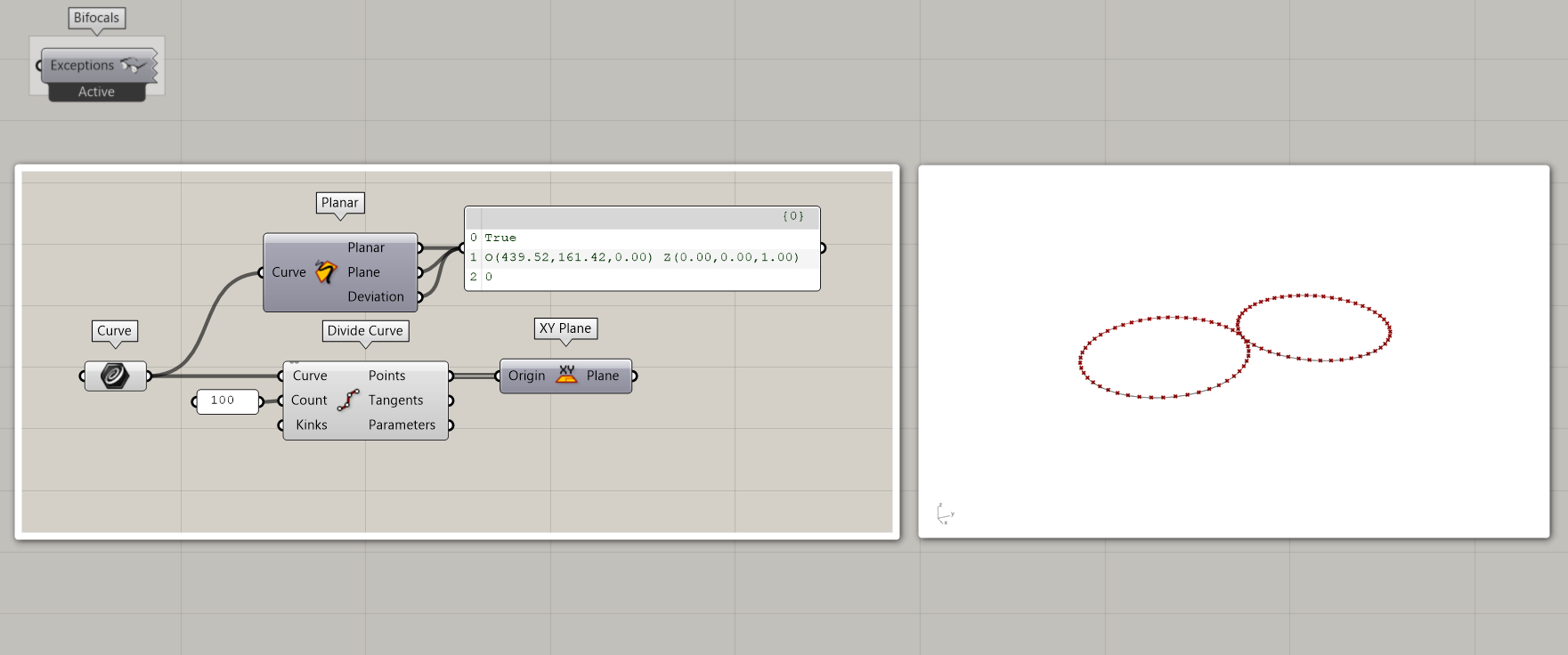
Axis focuses on robot control rather than toolpath generation—that’s handled by Grasshopper’s existing geometry tools. For example, a drawing application might start with a guide curve divided into points, with tool orientation defined by planes at each point. Every aspect can be customized, from tool angles to rotations.
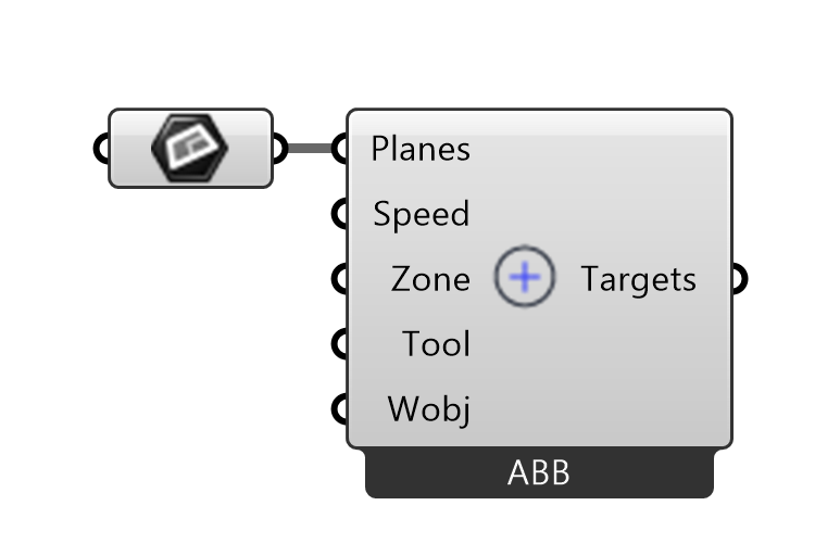
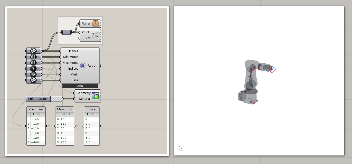
To create a plane target the user would typically need to provide 5 parameters, though Axis will provide conservative defaults to get users quickly up and running. The five parameters are: pose, speed, zone, tool and work object.
Speed and zone parameters control motion quality. Speed is straightforward, but zones deserve attention: they define a spherical tolerance around each target. Larger zones allow the robot to smooth its path, trading precision for speed and fluid motion.
The tool and work object parameters specify which end effector is attached and in which coordinate system the robot operates. Work objects are typically calibrated local coordinate systems around the workpiece, providing increased precision for the specific task.
Simulate Before Building
Before exporting code to a physical robot, Axis provides real-time 3D simulation. You see the robot move through your toolpath, point by point, with visual feedback on reachability, singularities, and joint limits. Axis does this by first calculating the inverse kinematics for all plane targets, which results in the 6 joint angles and then applies forward kinematics to the underlying mesh representation of the robot.
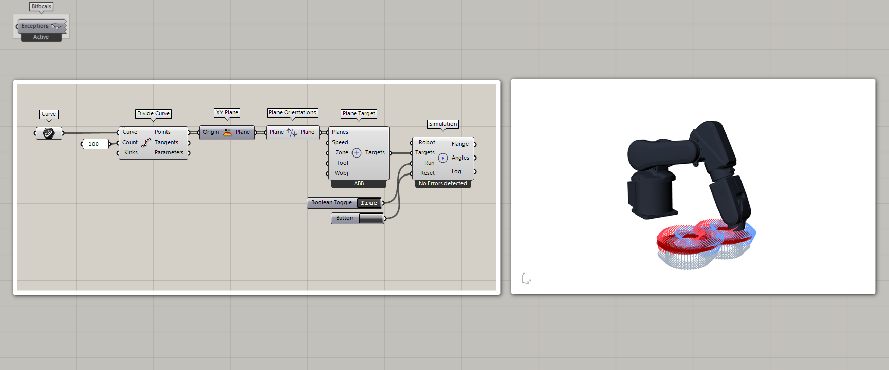
This simulation isn’t just visual — it’s computational validation. The geometric inverse kinematics solver, which uses sphere-sphere intersection rather than iterative numerical methods, is both elegant and fast. For each plane target, it calculates potential joint configurations in real time, flagging any that would push the robot into singular configurations or beyond its workspace.
Error detection at this stage saves time and material. Unreachable targets, wrist singularities, and motion planning issues surface here, not at the physical robot where they’d halt production.
Generate Production Code
Once your toolpath simulates cleanly, the Code Generation component produces production-ready RAPID code for ABB controllers. This isn’t simple trajectory translation—the code generator handles RAPID’s module system, automatically splits large programs to respect ABB file size limitations, and organizes procedures for clarity.
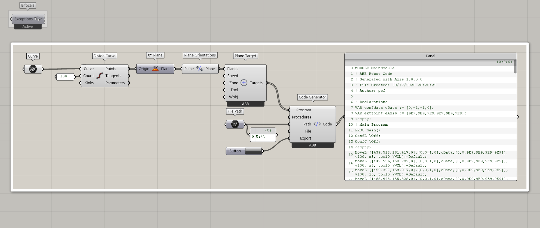
Export to a USB drive, transfer to the robot controller, and your parametric design becomes physical reality. The generated code includes all necessary declarations for speeds, zones, and tools, properly formatted for the ABB controller’s syntax requirements.
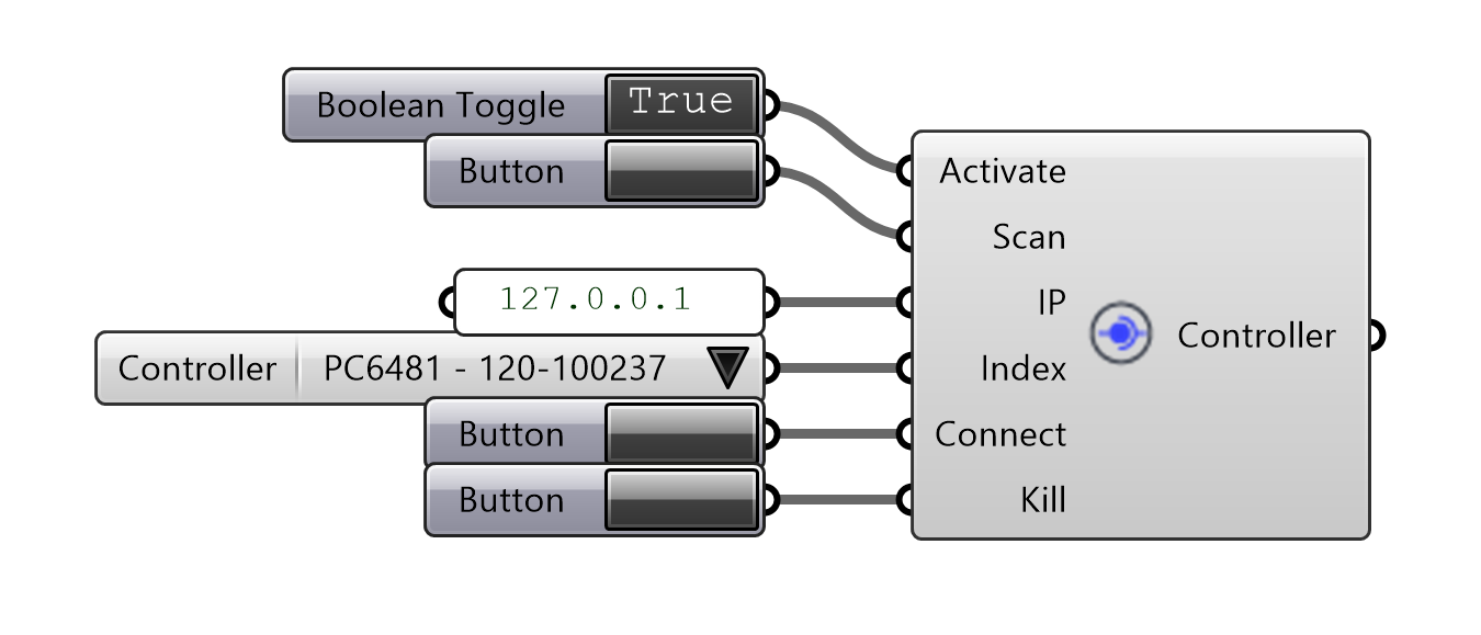
Live Control (Advanced)
For more interactive workflows, Axis supports real-time streaming instructions to ABB IRC5 controllers. This bidirectional communication uses a message-based protocol (RMQ) for low-latency instruction delivery and state monitoring.
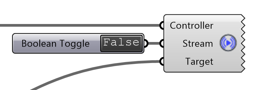
The architecture is sophisticated: a custom RAPID module runs on the controller, handling message queuing and trap-based interrupts. This enables parametric fabrication where you adjust design parameters and watch the robot respond in real time.
The system also supports monitoring—querying TCP position, joint angles, and I/O signals while the robot operates. This creates feedback loops: the robot’s state can inform design decisions, or trigger adaptive behaviors in your Grasshopper definition.
With great power comes responsibility: live control requires careful attention to safety protocols, collision zones, and emergency stop accessibility.
Extensibility & Technical Highlights
Customization
Axis defaults to MoveL instructions, which linearly interpolate between target points. Context menus and expanding inputs allow users to specify alternative motion types like MoveJ (joint angle interpolation), control additional linear and rotary axes, and define custom procedures. Custom tools and robot configurations can also be defined to match specific hardware setups.
This extensibility means Axis isn’t limited to the library of built-in ABB models. If you have a custom cell, an unusual robot, or modified end-of-arm tooling, you can model it accurately.